As you drive around town, you’ve probably noticed an increase in the number of hybrid electric vehicles (HEVs) on the road. Chances are you own one yourself. What is it about HEVs that is making them increasingly popular? In Part 1 of this article (AMT News, November 2013), we defined a technology as more sustainable than its competitors if it can provide more value with less environmental, financial and social costs. The genius of HEVs is that they are designed to switch between or combine two propulsion systems to maximize performance and fuel efficiency as a function of driving conditions. Even though they carry a bigger price tag, studies are revealing that, in the long run, HEVs are more cost-effective (and environmentally friendly) than equivalent conventional vehicles. Machine tool builders can take a clue from HEVs to come up with more sustainable designs. For instance, the traditional method for driving machine tool linear axes is to use a screw mechanism powered by a rotary motor. However, linear motor drives (LMDs) can achieve higher speeds and accelerations than screw drives (SDs). They also are not plagued by the inaccuracies caused by geometric errors, wear, backlash and structural deformations of the screw.Despite their performance advantages over SDs, LMDs have not gained widespread adoption in many high-speed machine tools. A key reason for this is because they don’t provide any mechanical advantage, and so they need to be oversized to support cutting loads. During cutting, their lack of mechanical advantage also makes them consume a lot of energy, which is largely dissipated in the form of heat that must be removed using expensive (and high-energy-consuming) cooling systems. The net result is an expensive machine, which costs a lot to run. Can one lower the cost and energy consumption of LMDs without sacrificing their performance by exploiting the power of synergy? Figure 1 (below) shows a hybrid feed drive (HFD) prototype we have designed to explore this question. The idea behind the HFD is to: (i) drive the machine table using a LMD during rapid traverse to achieve very high speeds and acceleration with low energy consumption; (ii) drive the table using a low-lead SD during cutting to achieve the required cutting speeds with low energy consumption; (iii) use the LMD to compensate for vibrations and errors introduced by the SD during cutting; and (iv) ensure that the switch between the LMD and SD can be achieved rapidly at any position of the table within its travel. In our HFD, an air core linear motor is employed to drive the table because it does not need to support large cutting forces, for which iron core motors are better suited. This saves costs and reduces performance issues related to using iron core motors.


To facilitate easy engagement and disengagement of the SD from the table, a rolling helix (or Roh’lix®) nut is utilized. The Roh’lix® nut converts rotary motion to linear motion using rolling element ball bearings that trace a screw motion (of lead = 5 mm) along a smooth shaft of 25 mm in diameter and 965 mm in length. It is designed to carry up to 444 N of thrust force without slippage between the nut and shaft. The Roh’lix® nut comes in two spring-loaded halves that can be separated to disengage the smooth shaft from the nut at any given location. A simple toggle mechanism is designed to separate the two halves of the nut using a pair of fast-acting pneumatic pistons. The controller for the HFD is designed to switch between a rapid traverse mode and cutting mode. In rapid traverse mode, the two halves of the Roh’lix® nut are opened and the controller controls the LMD only. In cutting mode, the nut is closed and the controller controls the SD to provide primary motion, while using the LMD to cancel the vibration and errors induced by the SD. The HFD has been shown in experiments to achieve similar speeds as LMDs. With the nut open, it can travel at rapid traverse speeds of up to 150 m/min, achieve 2.5 g of acceleration and ready itself for cutting (by closing the nut) within 0.2 seconds of reaching the target position. Such speeds and accelerations are extremely difficult to achieve in SDs. An ultra-high-lead SD (with low mechanical advantage) will have to be spun at very high speeds, consuming a lot of energy, and generating a lot of heat, wear and vibrations in the process. The benefits of pairing the LMD and SD during cutting have been demonstrated experimentally using a cutting test. The HFD, mounted on the x axis of a 3-axis milling machine, is used to cut a 4 mm long, 1.5 mm deep slot in an AISI 1018 steel workpiece with spindle speed of 3000 rpm using a 3/8” 4 fluted HSS end mill fed at 0.025 mm per tooth. The single-axis feed motion needed to create the slot is provided by either the LMD or by the HFD (i.e., LMD + SD).


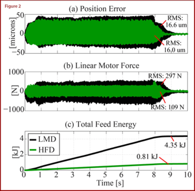
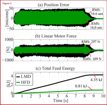
From Figure 2, we see that the LMD and HFD have very similar position errors during cutting, which confirms the equivalence of their accuracy. Based on the force from the LMD, the RMS feed force is 297 N, with maximum force levels of about 500 N. When the HFD is used, the linear motor does not have to support the entire cutting load therefore its RMS force drops to 109 N while the SD supports the rest of the load. As a result, the HFD uses about five times less energy (and has an estimated seven times less heat generation) to complete the operation compared to the LMD. So, much like its four-wheeled counterpart, the HFD holds promise to achieve high performance with much less environmental and economic costs. Our current research is focused on further improving the performance and energy efficiency of the HFD through improved mechanical and controller designs. Dr. Chinedum Okwudire is the Director of the University of Michigan’s Mechatronics and Sustainability Research (MSR) lab and has provided the members of AMT with a summary of sustainability research ongoing in his lab. If you have any questions, please contact Tim Shinbara at 703-827-5243 or tshinbara@AMTonline.org or Dr. Chinedum Okwudire at okwudire@umich.edu.


